Williams Sound IC-1 interpreter console
technical specifications
Dimensions, Weight: |
7" (17.7 cm) W x 5.625" (14.3 cm) D x 3.125" (9.3 cm) H, 1.82 lbs. (.83 kg) |
Color: |
Beige epoxy paint with black legends, blue bottom and side panels |
Power: |
External power supply, 12 VAC, 50 or 60 Hz, 10 VA, (TFP 008 Power Supply) (A 240 VAC Power Supply is also available, TFP 008 HV) |
Inputs |
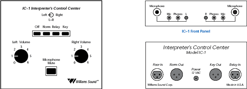
Floor In, Relay In: |
3-Pin XLR female jack, balanced or unbalanced line-level, Max 3.8 Vrms, Gain 6 dB, 43 k½ input impedance |
1/4" Microphone Inputs: |
Left and right, 1/4" TRS phone jack, balanced or unbalanced
microphone-level, Max 70 mVrms, Gain 46 dB, Supplies simplex DC power for electret microphones, 1.75 k½ input impedance |
3.5 mm Microphone Inputs: |
Left and right, 3.5 mm TRS phone jack, unbalanced (T,S) for condenser microphones, Max 70 mVrms, Gain 46 dB, Supplies DC power on tip, 1.75 k½ input impedance |
|
Outputs |
Key Out, Norm Out: |
3-Pin XLR male jack, balanced or unbalanced line-level, 7.7 Max Vrms, 56 ½ source impedance |
Phones: |
3.5 mm TRS phone jack, mono or stereo headphone, 8-32 ½, 63.7 mW at 8 ½ load max |
|
Controls |
Volume: |
Left and right, rotary, controls headphones volume |
Microphone Switch: |
3–way toggle. Selects left microphone, right microphone, or both |
Mute Switch: |
Push button. Mutes left and right microphones when depressed |
Function Switch: |
4-way push button. Selects OFF, NORM, RELAY, or KEY modes |
OFF Mode: |
Floor input (FLOOR IN) is fed to the interpreter’s headphones to allow monitoring of the meeting. Interpreter’s microphones are muted. |
NORM Mode: |
Floor input (FLOOR IN) is fed to the interpreter’s headphones. The selected interpreter’s microphone is fed to the normal output (NORM OUT). |
RELAY Mode: |
Interpreter monitors the relay input (RELAY IN) while the selected microphone feeds the normal output (NORM OUT). |
KEY Mode: |
Used to feed a second language audience. The interpreters monitor the floor input (FLOOR IN) while microphones feed the key output (KEY OUT). |
Feedthru Jumpers: |
Located on bottom of cabinet. Used to select floor signal feedthru options. |
J1 |
Feeds the floor signal to the normal output (NORM OUT). |
J2 |
Feeds the floor signal to the key output (RELAY OUT) |
Architect and Engineer Specifications
The unit shall be 7 inches wide, 55⁄8 inches deep, and 31⁄8 inches tall. The unit shall weigh 1.82 lbs.
The module shall be painted beige with black legends indicating controls, inputs, and outputs. The bottom and side panels shall be painted blue.
The power supply shall be external, 12 VAC, 50 or 60 Hz, 10 VA. An optional 240 VAC Power Supply shall also be available.
Inputs shall be configured as follows:
The “Floor In” and “Key In” inputs shall be 3-Pin, XLR female jacks, allowing balanced or unbalanced line-level inputs.
Maximum input levels shall be 3.8 Vrms. Gain shall be 6 dB with 43 k½ input impedance.
There shall be two microphone inputs, both 1⁄4" TRS phone jacks, balanced or unbalanced. These inputs shall be
microphone-level, allowing a maximum 70 mVrms and 46 dB gain. The two microphone inputs shall supply simplex DC power for electret microphones
with 1.75 k½ input impedance.
There shall be two independent 3.5 mm TRS microphone inputs (unbalanced (T,S) for condenser microphones), allowing a maximum 70 mVrms. Gain shall be 46 dB. The two 3.5 mm inputs shall supply DC power on tip, 1.75 k½ input impedance.
Outputs
The Key Out and Norm Out outputs shall be 3-Pin XLR male jacks, balanced or unbalanced line-level. Maximum output shall be 7.7 Vrms.
Source impedance shall be 56 ½.
There shall be two independent 3.5 mm TRS headphone output jacks (left / right).
The headphone outputs shall allow the use of either mono or stereo headphones, 8-32 ½. Maximum power shall be 63 mW at 8 ½.
Controls
The unit shall have two, independent rotary-type volume controls, controlling headphone volume.
The Microphone switch shall be a 3–way toggle type, selecting left microphone, right microphone, or both.
The mute switch shall be a push button-type, muting left and right microphones when depressed.
The function switch shall be a 4-way push button-type, selecting OFF, NORM, RELAY, or KEY modes.
Feedthru jumpers used to select floor signal feedthru options shall be located on bottom of cabinet.
The unit shall be Williams Sound Corp. Interpreter Control Center, Model IC-1.
IC-1
IC-1 Specifications
IC-1 Spec Sheet (PDF)
IC-1 Installation & User's Manual (PDF)
|